


Do you know any of the seven methods of knife alignment?
CNC lathe tool alignment is an important skill in machining, and the accuracy of tool alignment determines the machining accuracy of parts. Tool alignment efficiency directly affects the machining efficiency of parts, and tool alignment is very important for machine tool machining operations.
After the CNC lathe is turned on, a zero return (reference point) operation must be performed to establish a unified reference for position measurement, control, and display of the CNC lathe, that is, the tool returns to the machine tool origin. The machine tool origin is usually at the maximum positive stroke of the tool, and its position is determined by the machine position sensor.
After the machine tool returns to zero, the distance between the position of the tool (tool tip) and the machine tool origin is fixed and unchanged. Therefore, for the convenience of tool alignment and processing, the position of the tool tip after the machine tool returns to zero can be regarded as the machine tool origin. Tool alignment is the process of establishing a workpiece coordinate system in the machine coordinate system of a CNC machine tool, and making the origin of the workpiece coordinate system coincide with the programming origin.
Measure the distance between the tool tip programming point in the machine coordinate system and the machining origin in the X and Z directions through trial cutting or non-contact methods, and set the numerical value to the machine tool parameters. Through program calls, establish the workpiece coordinate system. The absolute coordinate value of the base point in the program is based on the origin of the established workpiece coordinate system, and process the contour of the part.
1, Principle of knife alignment
The purpose of tool alignment is to establish the workpiece coordinate system. Intuitively speaking, tool alignment is to establish the position of the workpiece in the machine tool workbench, which is actually to calculate the coordinates of the tool alignment point in the machine tool coordinate system.
For CNC lathes, the first step before machining is to select the tool alignment point, which refers to the starting point of the tool's relative motion to the workpiece when using the CNC machine tool to process the workpiece. The tool alignment point can be set on the workpiece (such as the design reference or positioning reference on the workpiece), as well as on the fixture or machine tool. If it is set at a certain point on the fixture or machine tool, the point must maintain a certain degree of precision dimensional relationship with the positioning reference of the workpiece.
When aligning the tool, the tool point should coincide with the tool point. The so-called tool point refers to the positioning reference point of the tool, and for turning tools, its tool point is the tool tip. The purpose of tool alignment is to determine the absolute coordinate value of the tool alignment point (or workpiece origin) in the machine coordinate system, and measure the tool position deviation value of the tool. The accuracy of tool point alignment directly affects the machining accuracy.
In actual machining of workpieces, using one cutting tool generally cannot meet the machining requirements of the workpiece, and multiple cutting tools are usually used for machining. When using multiple turning tools for machining, there will be differences in the geometric position of the tool tip point after the tool change, while the tool change position remains unchanged. This requires different tools to ensure the normal operation of the program when starting machining at different starting positions.
In order to solve this problem, the CNC system of the machine tool is equipped with a tool geometric position compensation function. By using the tool geometric position compensation function, as long as the position deviation of each tool relative to a pre selected reference tool is measured in advance, it is input into the designated group number in the tool parameter correction column of the CNC system. In the machining program, the tool position deviation can be automatically compensated in the tool path using the T command. The measurement of tool position deviation also needs to be achieved through tool alignment operation.
2, Knife alignment method
In CNC machining, the basic methods of tool alignment include trial cutting method, tool alignment instrument, and automatic tool alignment. This article takes CNC milling machines as an example to introduce several commonly used tool alignment methods.
1. Trial cutting and knife matching method
This method is simple and convenient, but it will leave cutting marks on the surface of the workpiece and has low tool accuracy. Taking the tool alignment point (which coincides with the origin of the workpiece coordinate system) at the center position of the workpiece surface as an example, the double-sided tool alignment method is adopted.
(1) Align the knife in the x and y directions.
① Install the workpiece onto the workbench through a fixture, and during clamping, leave positions for tool alignment on all four sides of the workpiece.
② Start the spindle to rotate at a medium speed, quickly move the worktable and spindle, allowing the tool to move quickly to a safe distance near the left side of the workpiece, and then reduce the speed to move closer to the left side of the workpiece.
③ When approaching the workpiece, use a fine-tuning operation (usually 0.01mm) to approach it, allowing the tool to slowly approach the left side of the workpiece, so that the tool precisely contacts the surface on the left side of the workpiece (observe, listen to cutting sounds, look for cutting marks, look for chips, and any situation that occurs indicates the tool is in contact with the workpiece), and then move back 0.01mm. Record the coordinate values displayed in the machine coordinate system at this time, such as -240.500.
④ Retract the tool in the positive z-direction until it reaches above the surface of the workpiece. Use the same method to approach the right side of the workpiece and record the coordinate value displayed in the machine coordinate system at this time, such as -340.500.
⑤ Based on this, the coordinate value of the origin of the workpiece coordinate system in the machine coordinate system is {-240.500+(-340.500)}/2=-290.500.
⑥ Similarly, the coordinate value of the workpiece coordinate system origin in the machine coordinate system can be measured.
(2) Z-direction knife alignment.
① Quickly move the tool above the workpiece.
② Start the spindle to rotate at a medium speed, quickly move the worktable and spindle, allowing the tool to move quickly to a safe distance near the surface of the workpiece, and then reduce the speed to move the tool end face close to the surface of the workpiece.
③ When approaching the workpiece, use a fine-tuning operation (usually 0.01mm) to approach it, allowing the tool end face to slowly approach the surface of the workpiece (note that when the tool, especially the end mill, it is best to lower the tool at the edge of the workpiece, and the area of the tool end face in contact with the workpiece surface is less than a semicircle. Try not to lower the center hole of the end mill on the surface of the workpiece), so that the tool end face exactly touches the upper surface of the workpiece, then raise the shaft again and record the z value in the machine coordinate system at this time, -140.400, then the coordinate value of the workpiece coordinate system origin W in the machine coordinate system is -140.400.
(3) Input the measured values of x, y, and z into the storage address G5 * of the machine tool workpiece coordinate system (usually using codes G54 to G59 to store tool alignment parameters).
(4) Enter panel input mode (MDI), enter "G5 *", press the start button (in automatic mode), and run G5 * to make it effective.
(5) Check if the knife alignment is correct.
2. Feeler gauge, standard core rod, block gauge for tool matching method
This method is similar to the trial cutting tool alignment method, except that the spindle does not rotate during tool alignment. A feeler gauge (or standard core rod, block gauge) is added between the tool and the workpiece, and the feeler gauge cannot be freely moved. Note that when calculating coordinates, the thickness of the feeler gauge should be subtracted. Because the spindle does not need to rotate for cutting, this method will not leave marks on the surface of the workpiece, but the tool accuracy is not high enough.
3. Using tools such as edge finders, eccentric rods, and axis setters to adjust the cutting method
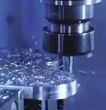
The operation steps are similar to using the trial cutting method, except that the tool is replaced with an edge finder or eccentric rod, which is the most commonly used method. High efficiency, ensuring tool alignment accuracy. When using the edge finder, care must be taken to make slight contact between the steel ball part and the workpiece. At the same time, the workpiece being processed must be a good conductor, and the positioning reference surface must have good surface roughness. The Z-axis setter is generally used to transfer (indirectly) the knife method.
4. Transfer (indirect) knife technique
Processing a workpiece often requires the use of more than one knife. The length of the second knife is different from the length of the first knife, and it needs to be re zeroed. However, sometimes the zero point is machined out, making it impossible to directly find the zero point, or it is not allowed to damage the already machined surface. In some cases, it is difficult to directly align the knife with the second knife. In this case, indirect zeroing can be used.
(1) To the first knife
① When using the first knife, still use trial cutting method, feeler gauge method, etc. first. Record the machine coordinate z1 of the workpiece origin at this time. After the first knife is processed, stop rotating the spindle.
② Place the tool aligner on a flat surface of the machine tool workbench (such as the large surface of a vice).
③ In handwheel mode, use hand cranking to move the workbench to the appropriate position, move the spindle downwards, press the bottom of the knife against the top of the tool setter, and rotate the dial pointer within one turn, preferably within one circle. Record the reading of the axis setter at this time and reset the relative coordinate axis to zero.
④ Raise the spindle and remove the first knife.
(2) For the second knife.
① Install the second knife.
② In handwheel mode, move the spindle downwards and press the bottom end of the knife against the top of the tool holder. The dial pointer rotates and points to the same reading position A as the first knife.
③ Record the value z0 (with a sign) corresponding to the relative coordinates of the axis at this time.
④ Raise the spindle and remove the tool aligner.
⑤ Add z0 (with a sign) to the z1 coordinate data in G5 * of the original first knife to obtain a new coordinate.
⑥ This new coordinate is the actual coordinate of the machine tool corresponding to the workpiece origin of the second tool to be found. It is input into the G5 * working coordinate of the second tool, so that the zero point of the second tool is set. The alignment method for the other knives is the same as that for the second knife.
Note: If several knives use the same G5 *, steps ⑤ and ⑥ should be changed to store z0 in the length parameter of the second knife, and when using the second knife for machining, the tool length correction G43H02 can be called.
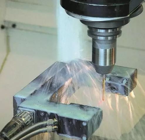
5. Top-notch knife technique
(1) Align the knife in the x and y directions.
① Install the workpiece onto the machine tool workbench through a fixture and replace it with a top.
② Quickly move the workbench and spindle to move the tip above the workpiece, find the center point of the workpiece's drawing line, and reduce the speed to move the tip closer to it.
③ Use fine-tuning operation to slowly approach the center point of the workpiece drawing line until the tip of the tip aligns with the center point of the workpiece drawing line. Record the x and y coordinate values in the machine coordinate system at this time.
(2) Remove the tip, install the milling cutter, and use other tool alignment methods such as trial cutting and feeler gauge to obtain the z-axis coordinate value.
6. Dial gauge (or micrometer) knife method
Dial gauge (or micrometer) tool alignment method (generally used for tool alignment of circular workpieces)
(1) Align the knife in the x and y directions.
Install the installation rod of the dial gauge on the tool handle, or suction the magnetic seat of the dial gauge onto the spindle sleeve. Move the workbench to move the spindle centerline (i.e. the tool center) approximately to the center of the workpiece. Adjust the length and angle of the telescopic rod on the magnetic seat so that the contact of the dial gauge contacts the circumferential surface of the workpiece (the pointer rotates by about 0.1mm). Slowly rotate the spindle by hand to make the contact of the dial gauge rotate along the circumferential surface of the workpiece, Observing the movement of the dial indicator pointer, slowly move the axis and shaft of the workbench. After multiple repetitions, when the spindle is turned, the pointer of the dial indicator is basically in the same position (when the gauge head rotates one revolution, the pointer's runout is within the allowable tool alignment error, such as 0.02mm). At this time, it can be considered that the center of the spindle is the origin of the axis and shaft.
(2) Remove the dial gauge and install the milling cutter. Use other tool alignment methods such as trial cutting and feeler gauge to obtain the z-axis coordinate value.
7. Special tool alignment method
The traditional tool alignment method has disadvantages such as poor safety (such as using a feeler gauge to align the tool, which can easily damage the tool tip due to hard impact), high machine time consumption (such as repeated cutting for trial cutting), and large random errors caused by human factors. It can no longer adapt to the rhythm of CNC machining and is not conducive to fully utilizing the functions of CNC machine tools. The use of specialized tool aligners for tool alignment has advantages such as high accuracy, high efficiency, and good safety. It simplifies the tedious tool alignment work that relies on experience and ensures the efficient and high-precision characteristics of CNC machines. It has become an indispensable special tool for solving tool alignment on CNC machining machines.


