


One article to understand! Common tool problems and countermeasures in CNC machining!
For machining centers, cutting tools are consumable tools that can cause damage, wear, and chipping during the machining process. These phenomena are inevitable, but there are also controllable reasons such as unscientific and non-standard operations, improper maintenance, etc. Only by finding the root cause can we better solve the problem.
one
The manifestation of tool damage
1) Cutting edge micro collapse
When the material structure, hardness, and margin of the workpiece are uneven, the front angle is too large, resulting in low cutting edge strength, insufficient rigidity of the process system causing vibration, or intermittent cutting, and poor grinding quality, the cutting edge is prone to micro collapse, that is, small collapse, notch or peeling in the edge area. After this situation occurs, the tool will lose some cutting ability but can still continue to work. During further cutting, the damaged part of the cutting edge area may rapidly expand, leading to greater damage.
2) Cutting edge or tip breakage
This type of damage often occurs under cutting conditions that are more severe than causing micro chipping on the cutting edge, or further development of micro chipping. The size and range of the fracture are larger than those of micro fractures, causing the tool to completely lose its cutting ability and have to terminate work. The situation where the blade tip breaks is often referred to as falling off the tip.
3) Blade or tool breakage
When the cutting conditions are extremely harsh, the cutting amount is too large, there is an impact load, and there are micro cracks in the blade or tool material. Due to residual stress in the blade caused by welding and grinding, combined with careless operation, it may cause the blade or tool to break. After this form of damage occurs, the tool cannot continue to be used and is therefore scrapped.
4) Blade surface peeling
For materials with high brittleness, such as hard alloys with high TiC content, ceramics, PCBN, etc., due to defects or potential cracks in the surface structure, or residual stress in the surface due to welding and grinding, surface peeling is prone to occur when the cutting process is not stable enough or the tool surface is subjected to alternating contact stress. Peeling may occur on the front blade surface, while the blade may occur on the back blade surface. The peeling material is in the form of flakes, with a large peeling area. There is a high possibility of peeling off of coated cutting tools. After slight peeling of the blade, it can still continue to work, but after severe peeling, it will lose cutting ability.
5) Plastic deformation of cutting parts
Due to their low strength and hardness, tool steel and high-speed steel may undergo plastic deformation in their cutting areas. When hard alloys work under high temperature and triaxial compressive stress, surface plastic flow can also occur, and even cause plastic deformation of the cutting edge or tool tip, resulting in collapse. Collapse generally occurs when cutting large amounts of material and processing hard materials. The elastic modulus of TiC based hard alloy is smaller than that of WC based hard alloy, so the former has an accelerated resistance to plastic deformation or rapid failure. PCD and PCBN generally do not exhibit plastic deformation.
6) Hot cracking of blades
When the cutting tool is subjected to alternating mechanical and thermal loads, the surface of the cutting part inevitably experiences alternating thermal stress due to repeated thermal expansion and contraction, leading to fatigue and cracking of the blade. For example, when a hard alloy milling cutter is used for high-speed milling, the cutter teeth are constantly subjected to periodic impacts and alternating thermal stresses, resulting in comb shaped cracks on the front cutting surface. Some cutting tools may not have obvious alternating loads and stresses, but due to the inconsistent temperature of the surface and inner layers, thermal stress will also occur. In addition, there are inevitably defects in the cutting tool material, so the blade may also produce cracks. After the formation of cracks, the tool can sometimes continue to work for a period of time, and sometimes the cracks rapidly expand, causing the blade to break or the cutting surface to peel off severely.
two
The reasons for tool wear
1) Abrasive wear
There are often tiny particles with extremely high hardness in the processed material that can scratch grooves on the surface of the tool, which is called abrasive sanding damage. Abrasive wear exists on all surfaces, with the front blade surface being the most pronounced. Moreover, hemp material wear can occur at various cutting speeds, but for low-speed cutting, due to the lower cutting temperature, the wear caused by other reasons is not significant, so abrasive wear is the main cause. The lower the hardness of the cutting tool, the more severe the abrasive damage.
2) Cold welding wear
During cutting, there is significant pressure and strong friction between the workpiece, cutting, and the front and rear cutting surfaces, resulting in cold welding. Due to the relative motion between the friction pairs, cold welding will cause rupture and be carried away by one side, resulting in cold welding wear. Cold welding wear is generally more severe at moderate cutting speeds. According to experiments, brittle metals have stronger resistance to cold welding than plastic metals; Multiphase metals are smaller than unidirectional metals; Metal compounds have a lower tendency towards cold welding compared to elemental materials; The tendency of B-group elements to cold weld with iron in the periodic table of chemical elements is small. Cold welding is more severe during low-speed cutting of high-speed steel and hard alloy.
3) Diffusion wear
During the cutting process at high temperatures and the contact between the workpiece and the tool, the chemical elements on both sides diffuse with each other in the solid state, changing the composition and structure of the tool, making the surface of the tool fragile and exacerbating tool wear. The diffusion phenomenon always maintains that objects with high depth gradients continue to diffuse towards objects with low depth gradients.
For example, cobalt in hard alloys rapidly diffuses into chips and workpieces at 800 ℃, while WC decomposes into tungsten and carbon and diffuses into steel; When PCD cutting tools are used to cut steel and iron materials, when the cutting temperature is above 800 ℃, the carbon atoms in PCD will transfer to the surface of the workpiece with great diffusion strength to form new alloys, and the tool surface will be graphitized. Cobalt and tungsten diffuse more severely, while titanium, tantalum, and niobium have stronger anti diffusion capabilities. Therefore, YT type hard alloys have good wear resistance. When cutting ceramics and PCBN, diffusion wear is not significant at temperatures as high as 1000 ℃ -1300 ℃. Due to the same material, workpieces, chips, and cutting tools will generate thermoelectric potential in the contact area during cutting, which promotes diffusion and accelerates tool wear. This type of diffusion wear under the action of thermoelectric potential is called "thermoelectric wear".
4) Oxidative wear
When the temperature rises, the surface of the tool oxidizes and produces softer oxides, which are rubbed by the chips and form wear called oxidation wear. For example, in the temperature range of 700 ℃ to 800 ℃, oxygen in the gas reacts with cobalt, carbides, titanium carbide, etc. in hard alloys to form softer oxides; PCBN undergoes a chemical reaction with water vapor at 1000 ℃.

three
The wear form of the blade
1) Front blade surface damage
When cutting plastic materials at a high speed, the area near the cutting force on the front cutting edge will wear into crescent pits under the action of chips, which is also known as crescent pit wear. In the early stage of wear, the rake angle of the tool increases, which improves the cutting conditions and is conducive to the curling and breaking of chips. However, when the crescent depression further increases, the cutting edge strength is greatly weakened, which may ultimately cause the cutting edge to break and be damaged. When cutting brittle materials or plastic materials with lower cutting speeds and thinner cutting thicknesses, there is generally no crescent pit wear.
2) Knife tip wear
The wear of the tool tip refers to the wear on the back face of the tool tip arc and the adjacent secondary back face, which is a continuation of the wear on the back face of the tool. Due to poor heat dissipation conditions and stress concentration here, the wear rate is faster than that of the rear cutting surface. Sometimes, a series of small grooves with a spacing equal to the feed rate are formed on the secondary rear cutting surface, which is called groove wear. They are mainly caused by the hardened layer and cutting patterns on the processed surface. When cutting difficult to cut materials with a high tendency to work hardening, it is most likely to cause groove wear. The wear of the tool tip has the greatest impact on the surface roughness and machining accuracy of the workpiece.
3) Rear blade wear
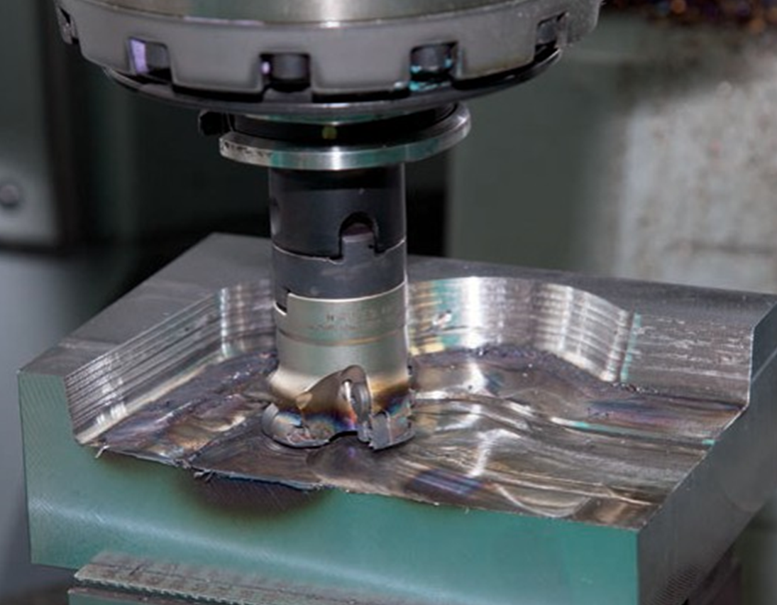
When cutting plastic materials with a large cutting thickness, due to the presence of chip deposits, the back face of the tool may not come into contact with the workpiece. In addition, the back cutting surface usually comes into contact with the workpiece, forming a wear band with a back angle of 0 on the back cutting surface. Generally, in the middle of the working length of the cutting edge, the wear on the back face is relatively uniform, so the degree of wear on the back face can be measured by the width of the wear band VB on the back face of the cutting edge in that section.
Due to the fact that various types of cutting tools almost always experience back face wear under different cutting conditions, especially when cutting brittle materials or plastic materials with smaller cutting thicknesses, the wear of the tool is mainly the back face wear. Moreover, the measurement of the width of the wear band VB is relatively simple, so VB is usually used to represent the degree of tool wear. The larger the VB, not only will it increase the cutting force and cause cutting vibration, but it will also affect the wear at the tool tip arc, thereby affecting the machining accuracy and surface quality.
four
Methods to prevent tool damage
1) Reasonably select the types and grades of tool materials based on the characteristics of the processed materials and parts. On the premise of having certain hardness and wear resistance, it is necessary to ensure that the tool material has the necessary toughness.
2) Reasonably select the geometric parameters of the cutting tool. By adjusting the front and rear angles, main and auxiliary deviation angles, blade inclination angles, and other angles; Ensure that the cutting edge and tip have good strength. Grinding negative chamfers on the cutting edge is an effective measure to prevent tool breakage.
3) Ensure the quality of welding and grinding, and avoid various defects caused by poor welding and grinding. The cutting tools used in key processes should be ground to improve surface quality and checked for cracks.
4) Reasonably choose the cutting amount to avoid excessive cutting force and high cutting temperature, in order to prevent tool damage.
5) Try to ensure that the process system has good rigidity and reduce vibration as much as possible.
6) Take the correct operating method and try to minimize the tool's ability to withstand sudden changes in load.
five
The causes and countermeasures of tool breakage
1. Improper selection of blade brand and specifications, such as blade thickness being too thin or selecting a brand that is too hard or too brittle during rough machining.
Countermeasure: Increase the thickness of the blade or install the blade vertically, and choose a brand with higher bending strength and toughness.
2. Improper selection of tool geometry parameters (such as large front and rear angles, etc.).
Countermeasures:
You can start redesigning the cutting tools from the following aspects.
1) Reduce the front and rear corners appropriately.
2) Use a larger negative blade inclination angle.
3) Reduce the main deflection angle.
4) Use larger negative chamfers or blade arcs.
5) Grinding the transition cutting edge to enhance the tool tip.
3. The welding process of the blade is incorrect, causing excessive welding stress or welding cracks.
Countermeasures:
1) Avoid using a three sided closed blade groove structure.
2) Correct selection of solder.
3) Avoid using oxyacetylene flames for heating welding, and maintain insulation after welding to eliminate internal stress.
4) Try to use mechanical clamping structures as much as possible
4. Improper grinding methods can cause grinding stress and cracks; The excessive vibration of the PCBN milling cutter teeth after grinding can cause excessive load on individual teeth and also lead to tool breakage.
Countermeasures:
1) Use intermittent grinding or diamond grinding wheel for grinding.
2) Choose a softer grinding wheel and regularly trim to keep the wheel sharp.
3) Pay attention to the quality of blade grinding and strictly control the vibration of the milling cutter teeth.
5. The selection of cutting amount is unreasonable. If the amount is too large, the machine tool may become stuck; When cutting intermittently, the cutting speed is too high, the feed rate is too large, and the cutting depth is too small when the blank allowance is uneven; When cutting materials with a high tendency for work hardening, such as high manganese steel, the feed rate is too small.
Countermeasure: Choose a new cutting amount.
6. Structural reasons such as uneven bottom surface of the groove or excessive extension of the blade for mechanical clamping type cutting tools.
Countermeasures:
1) Trim the bottom surface of the knife groove.
2) Reasonably arrange the position of cutting fluid nozzles.
3) Add a hard alloy gasket under the blade for the hardened tool holder.
7. Excessive tool wear.
Countermeasure: Change the tool or cutting edge in a timely manner.
Insufficient cutting fluid flow or incorrect filling method can cause sudden heating and cracking of the blade.
Countermeasures:
1) Increase the flow rate of cutting fluid.
2) Reasonably arrange the position of cutting fluid nozzles.
3) Use effective cooling methods such as spray cooling to improve the cooling effect.
4) Using * cutting to reduce the impact on the blade.
9. Incorrect installation of cutting tools, such as cutting tools installed too high or too low; The end face milling cutter adopts asymmetric forward milling and other methods.
Countermeasure: Reinstall the cutting tools.
10. The rigidity of the process system is too poor, causing excessive cutting vibration.
Countermeasures:
1) Increase the auxiliary support of the workpiece and improve the rigidity of the workpiece clamping.
2) Reduce the overhang length of the tool.
3) Reduce the back angle of the tool appropriately.
4) Adopt other vibration reduction measures.
11. Improper operation, such as excessive force when the tool cuts through the middle of the workpiece; Stop the vehicle before retracting the knife.
Countermeasure: Pay attention to operating methods.
six
The causes, characteristics, and control measures of debris accumulation tumors
1. Cause of formation
In the part near the cutting edge, within the tool chip contact area, due to the high downward pressure, the underlying metal of the chips is embedded in the micro uneven peaks and valleys on the front cutting surface, forming a true metal to metal contact without gaps and producing bonding phenomenon. This part of the tool chip contact area is called the bonding area. In the bonding zone, a thin layer of metal material will accumulate on the front cutting surface at the bottom layer of the chips, and the metal material of this part of the chips undergoes severe deformation and strengthening at an appropriate cutting temperature. As the chips continue to flow out, under the pushing force of the subsequent cutting flow, this layer of stagnant material will slip relative to the upper layer of the chips and leave, becoming the foundation of the chip accumulation lump. Subsequently, a second layer of hysteresis cutting material will be formed on top of it, which continuously accumulates and forms chip nodules.
2. Characteristics and their impact on cutting processing
1) The hardness is 1.5-2.0 times higher than that of the workpiece material, and it can replace the front cutting surface for cutting. It has the function of protecting the cutting edge and reducing the wear of the front cutting surface. However, when the debris falls off, it flows through the contact area between the tool and the workpiece, causing wear on the back cutting surface of the tool.
2) After the formation of chip deposits, the working rake angle of the tool significantly increases, which plays a positive role in reducing chip deformation and cutting force.
3) Due to the accumulation of chips protruding beyond the cutting edge, the actual cutting depth increases, affecting the dimensional accuracy of the workpiece.
4) The accumulation of debris can cause "plowing" on the surface of the workpiece, affecting the surface roughness of the workpiece.
5) The fragments of accumulated debris can adhere or embed into the surface of the workpiece, causing hard spots and affecting the quality of the processed surface of the workpiece.
From the above analysis, it can be seen that chip accumulation is unfavorable for cutting, especially for precision machining.
3. Control measures
To prevent the formation of chip deposits, the following measures can be taken to prevent the bonding or deformation strengthening between the chip substrate material and the front cutting surface.
1) Reduce the roughness of the front blade surface.
2) Increase the front angle of the tool.
3) Reduce cutting thickness.
4) Use low-speed cutting or high-speed cutting to avoid cutting speeds that are prone to chip buildup.
5) Properly heat treat the workpiece material to increase its hardness and reduce plasticity.
6) Use cutting fluids with good anti adhesive properties (such as extreme pressure cutting fluids containing sulfur and chlorine).


