Do you understand all these slow wire processing techniques?
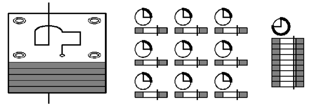
Coreless cutting, also known as chip free cutting, is a processing method in which the electrode wire follows a dense trajectory within the machining shape without generating any waste material when processing very small shapes. There are two methods of chip free machining, spiral path and parallel path, as shown in the following figure. When cutting without a core, the main cutting tool removes the entire shape and leaves a suitable margin for trimming processing.
If the coreless processing method is not used, the main cutting will produce very small waste, which is easy to fall into the lower nozzle. Firstly, it is difficult to pick up the waste, and secondly, it is easy to damage the lower nozzle when moving the axis, and even cause the workpiece to shift position, resulting in scrap. The purpose of using coreless cutting is mostly for the processing of small holes, and some people use coreless cutting to achieve the purpose of unmanned machines. Both 2D/3D paths can use coreless cutting.
02 Both male and female molds come out together
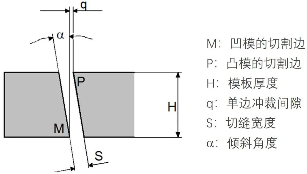
For the wire cutting processing of punching dies and cutting dies, if non tapered cutting is used, the width of the cutting seam is usually greater than the punching gap. Therefore, two materials need to be prepared to cut the convex die (male) and the concave die (female) separately. If we design a suitable angle for the template and use wire cutting for taper machining, we can process both convex and concave molds on a single template, which can greatly improve production efficiency and reduce material costs.
The punching gap value can be obtained based on the thickness of the product material, and the cutting gap width can be calculated based on the diameter of the electrode wire and the unilateral discharge gap. The thickness of the template is also known. With this data, the cutting angle required for wire cutting can be calculated. As shown, the formula for calculating the angle is: a=arctg [(S-q)/H]
03 Processing of mating parts
The processing of mating parts depends on selecting the correct electrode wire offset, appropriate mating clearance, and cleaning the sharp corners. The steps for processing mating parts are:
1) Processing convex molds. Cut a 10mm x 10mm punch using standard parameters and measure the dimensions. If the offset of the electrode wire used is 0.223, 0.164, 134, 0.129, and the measured size is 10.004mm, it can be seen that the size is 0.002mm larger on one side.
2) Adjust the offset. Due to the actual protrusion size being 0.002mm larger on one side, the electrode wire offset should be adjusted to 0.221, 0.162, 0.132, 0.127.
3) Calculate the offset of the machining die. The electrode wire offset of the standard concave and convex molds is the same. But the concave mold needs to subtract the clearance of one side fit. For slow wire processing, the gap for tight fitting is generally 0.002mm on one side, and the gap for smooth fitting is 0.005mm on one side. For example, if the clearance is 0.005mm, the electrode wire offset of the cutting die is 0.216, 0.157, 0.127, 0.122.
4) Cooperate to fit the convex mold into the concave mold, and ensure that the workpiece is placed vertically during the fit. Using slow wire cutting to process a clearance of 0.005mm on one side will result in a smoother fit.
04 Linear cutting
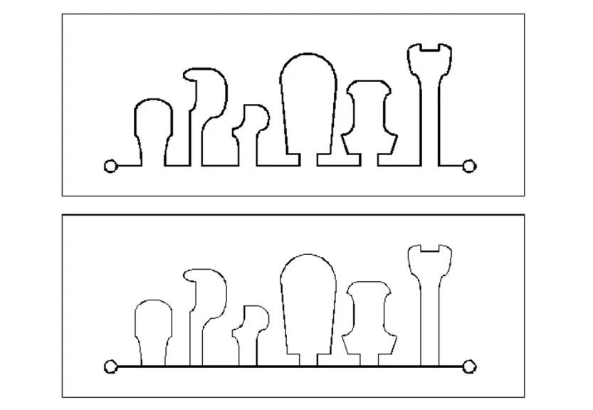
When it is necessary to use wire cutting to process a series of cylindrical convex molds, during programming, these convex mold shapes are designed on a template and kept connected to each other. Finally, they are linearly cut and separated, as shown in the following figure. This process is particularly suitable for long-term continuous cutting of small protrusions. The use of this process requires a reasonable arrangement, which can achieve the goal of saving materials and avoid cutting deformation.
05 Composite cutting
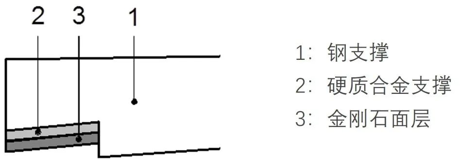
Composite cutting is the simultaneous cutting of workpieces composed of different materials. Composite cutting is mainly used for cutting different material combinations of punching dies, cutting different material combinations of punching and shearing dies, and cutting composite materials with forming turning tools, as shown in the following figure. For this type of cutting, cutting stability is an issue, and when selecting process parameters, it is possible to consider selecting materials with the thickest or most difficult to cut parts as the basis.
06 Stacking cutting
Stacking cutting refers to cutting a certain number of workpieces of the same shape and material in one go through the stacking of parts, as shown in the following figure. This process is used for cutting thin plate parts, and the overall efficiency of one-time large thickness cutting is much higher than that of single piece thin plate cutting. Fix the thin plate together with screws or conductive adhesive to form a whole block, ensuring conductivity between the various parts. In addition, the thickness of the stacking should not be too thick, preferably not exceeding 150mm, otherwise it will affect the machining accuracy of the consistency of the stacked parts.