


Analysis of the reasons for unreliable tool chip breakage and solutions
How much do you know about tool chip breaking knowledge? After reading this article, I believe it will be helpful for your daily work.
The reliability of tool chip breakage has a significant impact on normal production and operator safety. In cutting, broken chips can splash and harm people, and are prone to damage the machine tool; However, long strip shaped chips can wrap around the workpiece or tool, easily scratching the workpiece, causing tool damage, and even affecting worker safety.
For automated machining machines such as CNC machine tools (machining centers), due to the large number of cutting tools and the close connection between the tool holder and the tool, the problem of chip breakage becomes more important. As long as one of the cutting tools is unreliable, it may disrupt the automatic cycle of the machine tool and even disrupt the normal operation of the entire automatic line. Therefore, when designing, selecting or grinding tools, the reliability of tool chip breakage must be considered. For CNC machine tools (machining centers), etc., the following requirements should be met:
Chips shall not be entangled on cutting tools, workpieces, and adjacent tools and equipment;
Chips must not splash to ensure the safety of operators and observers;
During precision machining, chips should not scratch the machined surface of the workpiece, affecting the quality of the machined surface;
Ensure the predetermined durability of the cutting tools, avoid premature wear, and make every effort to prevent their damage;
When chips flow out, it does not hinder the injection of cutting fluid;
Chips will not scratch machine guides or other components.
On the basis of meeting the above requirements, different cutting tools have different requirements for chip length. For example, the maximum chip length for rough turning steel materials is generally around 100mm; A fine car should be slightly longer. To avoid overly fine chips, as they are easily embedded in important parts of the machine guide and tool device (such as the reference plane), this not only requires additional protective devices, but also poses certain difficulties in removing chips.
For certain cutting tools that are not prone to chip breakage, such as forming turning tools, slotting turning tools, and cutting turning tools, stable chip curling should be ensured on automated machine tools such as CNC machining centers.
one
Classification of chip shapes
According to the specific conditions of workpiece material, tool geometric parameters, and cutting amount, the shape of chips generally includes: strip chips, C-shaped chips, chipping chips, pagoda shaped chips, spring shaped chips, long and tight screw chips, screw chips, etc.
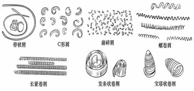
1. Banded debris
When high-speed cutting plastic metal materials, if no chip breaking measures are taken, it is easy to form strip shaped chips, which are continuous and often entangled on the workpiece or tool, easily scratching the surface of the workpiece or damaging the cutting edge of the tool, and even injuring people. Therefore, it is advisable to avoid forming strip shaped chips as much as possible.
But sometimes we also hope to get strip chips so that the chips can be discharged smoothly. For example, when boring blind holes on a vertical boring machine.
2. C-shaped debris
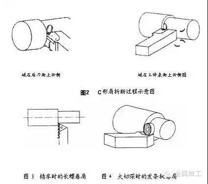
When turning general carbon steel and alloy steel materials, using a turning tool with a chip groove can easily form C-shaped chips. C-shaped chips have the disadvantage of strip chips. But most C-shaped chips are broken by colliding with the back face of the turning tool or the surface of the workpiece. The high-frequency collision and breakage of chips can affect the smoothness of the cutting process, thereby affecting the roughness of the machined surface. So, during precision machining, it is generally not desired to obtain C-shaped chips. Instead, it is more desirable to obtain long spiral coil chips to make the cutting process more stable.
3. Windmill shaped crumbs
Turning steel parts with large cutting depth and high feed rate on heavy-duty lathes results in wide and thick chips. If C-shaped chips are formed, they can easily damage the cutting edge and even cause flying and injuring people. So usually, the radius of the arc at the bottom of the chip groove is increased, so that the chips form hair strips and collide and break on the machining surface, and fall off by their own weight.
4. Long and tight crumbs
The formation process of long and tight chips is relatively stable, and cleaning is also convenient. It is a good chip shape on a regular lathe.
5. Pagoda shaped crumbs
When CNC machining, machine tools, or automatic line machining, it is desired to obtain this type of chip because it will not entangle with the tool and workpiece. And cleaning is also convenient.
6. Avalanche debris
When turning brittle materials such as cast iron, brittle brass, and cast bronze, needle shaped or fragmented debris is easily formed, which is prone to splashing and injuring people, as well as damaging the machine tool. If chip rolling measures are adopted, the chips can be connected into short rolls.
In short, the specific conditions of cutting processing are different, and the desired shape of the chips is also different. However, regardless of the shape of the chips, they must be reliably broken.
two
The principle of chip breakage
In the process of metal cutting, whether the chips are easy to break is directly related to the deformation of the chips. Therefore, studying the principle of chip breaking must start with studying the laws of chip deformation.
The chips formed during the cutting process, due to significant plastic deformation, will have an increase in hardness, while plasticity and toughness will significantly decrease. This phenomenon is called cold work hardening. After cold work hardening, the chips become hard and brittle, and are easily broken when subjected to alternating bending or impact loads. The greater the plastic deformation experienced by the chips, the more significant the brittle phenomenon, and the easier it is to break. When cutting materials with high strength, high plasticity, and high toughness that are difficult to break chips, efforts should be made to increase the deformation of the chips to reduce their plasticity and toughness, in order to achieve the goal of chip breaking.
The deformation of chips can be composed of two parts:
The first part is the basic deformation formed during the cutting process. The chip deformation measured during free cutting with a flat rake face turning tool is relatively close to the basic deformation value. The main factors affecting basic deformation include tool rake angle, negative chamfer, and cutting speed. The smaller the front angle, the wider the negative chamfer, and the lower the cutting speed, the greater the deformation of the chip, which is more conducive to chip breakage. Therefore, reducing the front angle, widening the negative chamfer, and reducing the cutting speed can be measures to promote chip breakage.
The second part is the deformation that chips undergo during the flow and curling process, which we refer to as additional deformation. Because in most cases, only the basic deformation during the cutting process cannot break the chips, and an additional deformation must be added to achieve the purpose of hardening and breaking. The simplest way to force chips to undergo additional deformation is to grind (or press) a certain shape of chip groove on the front cutting surface, forcing the chips to flow into the chip groove and then curl and deform. After undergoing additional re curling deformation, the chips further harden and become brittle. When they collide with the workpiece or the back cutting surface, they are easily broken.
three
The influence of chip breaking groove on chip breaking (rolling)
The chip breaking groove not only plays an additional deformation role on the chips, but also has an important impact on the shape and breaking of the chips. In cutting processing, people use the different shapes and sizes of chip grooves, as well as the inclination angle between the chip groove and the main cutting edge, to control the curling and breaking of chips. In order to better understand and master these rules, we will analyze in detail the shape and size of the chip groove, as well as the influence of the inclination angle between the chip groove and the main cutting edge on the chip shape and chip fracture.
1. The shape of the chip groove
There are three types of shapes for chip breaking grooves: straight arc, straight arc, and full arc.

(1) The straight and circular arc chip breaking groove is formed by connecting a straight line and a circular arc. The straight part forms the front face of the tool, and the size of the radius Rn of the groove bottom arc has a certain impact on the curling and deformation of the chips. If Rn is small, the chip curling radius is small, while the chip deformation is large; If Rn is large, the chip curling radius is large, while the chip deformation is small. At a moderate cutting depth (cutting depth ap=2-6mm), Rn=(0.4-0.7) B is generally selected, where B is the width of the chip groove.
(2) The linear chip groove is formed by the intersection of two straight lines, with a bottom angle of 180 °- σ ( σ Refers to as chip breaking platform wedge angle, groove bottom angle (180 °- σ) Replacing the function of arc Rn. If the bottom angle of the groove is small, the curling radius of the chips is small, and the deformation of the chips is large; If the bottom angle of the groove is large, the curling radius of the chips is large, and the deformation of the chips is small. At a moderate cutting depth, the wedge angle of the chip breaking table is generally selected from 60 ° to 70 °.
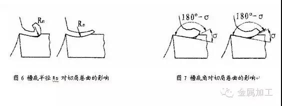
The above two types of chip cutting grooves are suitable for processing carbon steel and alloy structural steel, and the front corner is generally γ. Within the range of 5-15 °.
(3) The main parameters of a full arc chip breaking groove are groove width B, groove bottom arc radius Rn, and front angle γ. The relationship between them is:
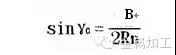
注:见图5C
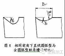
When cutting high plastic materials such as copper and stainless steel, a full arc chip breaking groove is often used. Because when processing high plastic materials, the tool rake angle is selected relatively large( γ The cutting edge of the full arc chip breaking groove tool with a front angle of the same size (0=25 °~30 °) is relatively sturdy, and the groove is also shallow, making it more practical for chip flow.
2. The width of the chip groove
The width B of the chip groove is related to the feed rate f and the cutting depth ap. When the feed rate f increases, the cutting thickness increases, and the width of the chip groove should be correspondingly widened; The cutting depth is large, and the groove should also be appropriately widened.
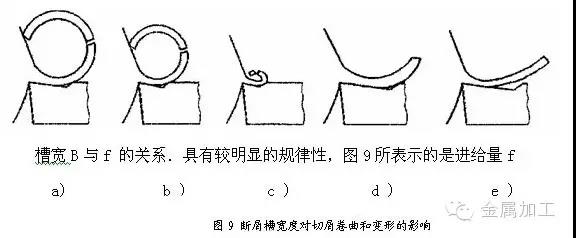
The effect of the change in chip groove width B on chip curling and deformation, which remains fixed and unchanged. Figure 9a shows that the groove width is basically adapted to the feed rate, and the chips are bent and deformed before colliding and breaking into a C-shape; Figure 9b shows that the groove is not wide enough, the chip curling radius is small, the deformation is large, and after collision, it breaks into a short C-shape or forms fragmented small pieces; Figure 9c shows that the groove is too narrow, and the chips are squeezed into small rolls and blocked in the groove, making it difficult to flow out, resulting in chip blockage and even damaging the cutting edge; Figures 9d and e show that the groove is too wide, the chip curling radius is too large, the deformation is not enough, and it is not easy to break. Sometimes, it does not even flow through the bottom of the groove and freely forms strip shaped chips.
If the width of the chip groove is initially selected using the feed rate, roughly speaking, for cutting medium carbon steel, the relationship between the width B and the feed rate f is about B=10f; When cutting alloy steel, to increase chip deformation, B=7f can be taken.
The width B of the chip groove should also be suitable for the cutting depth ap. Generally, slot width B can also be roughly selected based on ap, and when ap is large, B should also be larger; If ap is small, then B should be appropriately reduced. Because when the cutting depth is too deep and the groove is too narrow, the chips are wide and not easy to curl in the groove, so the chips often do not flow into the bottom of the groove and form strip shaped chips on their own; When the cutting depth is small but the groove is too wide, the chips are narrow, the flow is relatively free, the deformation is not sufficient, and it is not easy to break.
3. The inclination angle between the chip groove and the main cutting edge
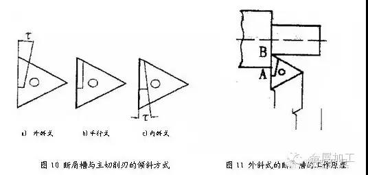
There are three commonly used tilting methods for the chip groove and the main cutting edge: external tilting, parallel tilting, and internal tilting.
(1) External oblique type
The outward sloping chip groove is wide in the front and narrow in the back, deep in the front and shallow in the back.
The chip curling deformation of the external inclined chip breaking groove is large, as shown in Figure 11. The cutting speed is highest near the outer surface A of the workpiece, and the groove is narrow. The chip is first obstructed and curled, with a small curling radius and large deformation; At the cutting edge B, the cutting speed is low and the groove is wide. The chips are finally curled with a larger curling radius, which generates a force that flips the chips onto the back cutting surface or the surface to be machined. After collision, they break and form C-shaped chips.
This form of chip groove. At moderate cutting depth, the chip breaking range is wide, the chip breaking effect is stable and reliable, and it is widely used in production. Inclination angle τ The value of is mainly determined by the material of the workpiece. Generally, when cutting medium carbon steel, it is taken as τ= When cutting alloy steel from 8 ° to 10 °, in order to increase chip deformation, take τ= 10 °~15 °.
However, during large cutting depths, due to the small width of the chip groove near the outer surface A of the workpiece (see Figure 11), the chips are prone to blockage and even damage the cutting edge. Therefore, parallel cutting is generally used instead.
(2) Parallel
The chip deformation of the parallel chip breaking groove is not as large as that of the external inclined groove, and most of the chips are broken when they collide with the machining surface of the workpiece.
When cutting carbon steel chips, the chip breaking effect of the parallel chip breaking groove is basically similar to that of the external inclined groove, but the feed rate should be slightly increased to increase the additional curling deformation of the chips.
(3) Internal oblique type
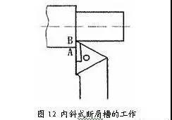
The internally inclined chip breaking groove (see Figure 12) is the widest at the outer surface A of the workpiece and the narrowest at the tool tip B. So the chips are often curled into small rolls at point B, and then into large rolls at point A. When the inclination angle of the main cutting edge is set at 3 °~5 °, the chips are prone to forming continuous and tight curls. The inclination angle between the internal inclined chip groove and the main cutting edge is generally taken as τ= The cutting range of the inner inclined chip breaking groove with a long and tight chip coil is quite narrow from 8 ° to 10 °, so its application in production is not as common as that of the outer inclined and parallel types, mainly used for precision turning or semi precision turning.
four
Several commonly used chip breaking methods
1. Utilize chip breaker
As mentioned earlier, the chip breaking groove not only plays an additional role in shaping the chips, but also enables control of chip curling and breaking. As long as the shape, size, and inclination angle between the chip groove and the main cutting edge are appropriate, chip breaking is reliable. Whether it is a welding type tool or a machine clamp type tool, it can be used as a regrinding type tool or a non regrinding type tool.
In order to adapt to different ranges of cutting quantities. There are various shapes and sizes of chip grooves on the hard alloy indexable blade, which are easy to choose and economical. This method is the preferred and most widely used method in cutting machining.
The shortcoming is that the determination of reasonable geometric parameters of the cutting tool is constrained by chip breaking requirements.
2. Using a chip breaker
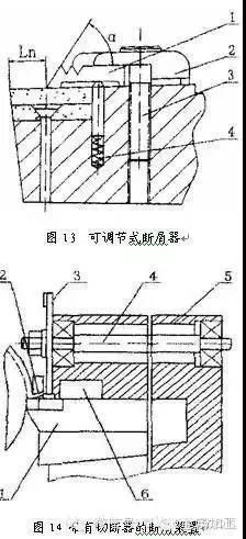
There are two types of chip breakers: fixed and adjustable. Figure 13 shows the adjustable chip breaker on the turning tool.
Install a chip guard plate 1 on the front cutting surface of the turning tool. When chips flow out along the front of the tool, they bend and break due to the resistance of the chip guard plate 1. The parameters Ln and α Can be designed and adjusted as needed to ensure stable and reliable chip breaking under given cutting conditions. Loosen screw 3, and under the action of spring 4, the chip guard plate 1 and pressure plate 2 can be lifted together, facilitating the adjustment of the chip guard plate and the quick rotation and replacement of the blade. This type of chip breaker is commonly used on cutting tools of large and medium-sized machine tools.
3. Utilizing chip breaking devices
There are many types of chip breaking devices, which can generally be divided into mechanical, hydraulic, and electrical types. Chip breaking devices have high costs, but they are stable and reliable, and are generally only used on automatic lines. Figure 14 is a schematic diagram of a chip breaking device with a cutter used on turning tools. During turning, the chips flow out through the chip guide channel 2 and are forcibly cut by the continuously rotating disc cutter 3. The cut chips are then discharged from the chip discharge channel 6. The cutter is driven by drive shaft 4. Figure 1 shows the turning tool.
4. The method of using pre grooving on the surface of the workpiece
According to the different diameters of the workpiece, one or several grooves are pre cut along the axial direction of the workpiece on the machined surface, with a depth slightly lower than the cutting depth, so that the cut chips form a weak section and break. This ensures reliable chip breakage without affecting the roughness of the machined surface of the workpiece. Even when processing materials with high toughness, the chip breaking effect is still very good. For example, in precision boring of workpiece materials with high toughness (such as 40Cr), when it is difficult to break chips using other methods, longitudinal grooves can be pulled out on the machined surface before boring. This method can demonstrate its unique advantages.
5. Changing tool geometry parameters and adjusting cutting parameters
From the chip breaking principle mentioned earlier, it can be inferred that reducing the tool rake angle; Increase the main deviation angle; Grinding negative chamfers on the main cutting edge; Reduce cutting speed; Increasing the feed rate and changing the shape of the main cutting edge can promote chip breakage. However, using these methods to break chips often brings some adverse consequences, such as a decrease in productivity, deterioration of workpiece surface quality, and increased cutting force. This method is rarely used on automatic lines and sometimes only serves as an auxiliary means of chip breaking.
In addition, the use of cutting fluid can reduce the plasticity and toughness of chips, and is also beneficial for chip breakage. Increasing the cutting fluid pressure can better promote chip breakage, and this method is sometimes used in hole machining.


