


What is the reason for the roundness error in the machining center? How to adjust?
In response to the frequent occurrence of parts exceeding tolerance due to roundness errors in the machining process of machining centers, in order to avoid such problems, the reasons for roundness errors are analyzed, and how to suppress such problems in actual machine tool processing to ensure the accuracy requirements of parts processing are discussed.
Roundness error refers to the variation of the actual circle of the object being measured within the same cross-section of the rotating body compared to the ideal circle. During long-term use of CNC machine tools, ball screws, guide rails, and bearings may experience some degree of wear. At the same time, factors such as inadequate maintenance, lack of lubrication, and large tool cuts can exacerbate the wear of mechanical components, leading to accelerated deterioration of geometric accuracy of CNC equipment. These are all factors that cause roundness errors. The unstable dynamic response and imperfect servo optimization of CNC systems can also affect the roundness error of CNC machine tools.
Generally, in the practical application of machine tools, roundness error detection of machining equipment can be carried out through a ball and rod tester or the equipment's built-in roundness testing function. The roundness testing function of the Siemens 840Dsl CNC system can simulate machining through CNC programs without the need for part trial cutting. With the powerful computing power and position feedback function of the CNC system, the actual and theoretical roundness errors of the machine tool can be measured. By analyzing the different graphics obtained from roundness testing, the reasons for different errors and the adjustment methods for such errors can be determined. The main causes of roundness errors generally include large reverse clearance of the interpolation axis, reverse jumping, servo mismatch, two interpolation axes not perpendicular, and machine tool vibration. Taking the Siemens 840Dsl CNC system as an example, the following will be explained.
one
Reverse clearance error
The reverse clearance error of a machine tool refers to the reverse clearance of the machine tool shaft, which is generally reflected in the helix angle of the screw in a semi closed loop CNC system. Although the driving motor drives the screw to reverse within a certain angle, the workbench still needs to wait for the clearance between the screw and the nut to be eliminated before it can move in reverse. This clearance is the reverse clearance of the machine tool shaft, which is generally reflected in the helix angle of the screw, The difference between the command value and the actual movement amount when the axis is in reverse motion is the reverse clearance error value of the axis.
(1) The influence of reverse clearance on roundness error can affect the positioning accuracy and repeated positioning accuracy of the machine tool, reduce the machining accuracy of CNC machine tools, and cause roundness error during the milling process of the machining center. When the Y-axis is in reverse motion, due to the presence of reverse clearance, it will cause the Y-axis to lag behind the X-axis for interpolation motion, resulting in the milling process as shown in Figure 1.
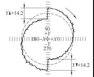 Figure 1 Roundness error caused by reverse clearance
(2) The measurement and adjustment of reverse clearance have various factors that affect the error of machine tool shaft reverse clearance. All mechanical connections between the driving motor and the moving parts will have clearances, and the reasons for the reverse clearance of the machine tool shaft are whether the coupling of the motor to the screw is loose, the manufacturing error of the ball screw, whether the pre tightening of the screw is too tight or too loose, and whether the connection between the screw nut and the moving part is tight. For clearances that cannot be eliminated in the mechanical part, it is necessary to compensate for the reverse clearance in the CNC system.
As shown in Figure 2, reverse clearance measurement is carried out by fixing a position with a magnetic gauge holder, pressing the dial gauge head onto a fixed position on the worktable where the shaft to be measured, zeroing the dial gauge scale, continuing to move the feed shaft in the same direction for a certain distance, moving the shaft in the opposite direction to the initial position, reading the difference A of the dial gauge. The average value obtained after 7 measurements is the reverse clearance error of the shaft, That is, A=(A1+A2+A3+A4+A5+A6+A7)/7. Writing the measured and calculated value A into the corresponding axis parameter MD32450 can eliminate the reverse clearance of this axis. By compensating for the reverse clearance of the shaft, the accuracy of the feed shaft can be effectively improved to ensure the accuracy of interpolation motion and effectively improve roundness error.
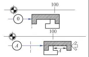 Figure 2 Measurement of reverse clearance
two
Machine tool feed shaft vibration
The vibration generated during CNC machining not only affects the dynamic accuracy of the machine tool, but also reduces the contour accuracy of the machined parts, increases the surface roughness value, and even affects the service life of the tool and machine tool when the vibration is severe. (1) The causes of vibration and its impact on roundness error in CNC machine tool feed systems are mainly due to three reasons: first, poor lubrication between moving parts, increased frictional resistance on moving parts, which can easily cause crawling and vibration of the feed shaft; Secondly, the overall stiffness of the mechanical transmission chain between the feed system drive device and the moving parts is poor; The third issue is that in closed-loop CNC systems, system oscillations are caused by excessive gain settings for position, speed, and current loops, as well as unreasonable parameter settings for acceleration. In the application process of CNC machine tools, the causes of vibration are usually comprehensive and should be investigated one by one. As shown in Figure 3, when the feed shaft of the machine tool vibrates, the tool and workpiece will experience periodic jumping, and the machined surface of the workpiece will randomly produce stripes with the same frequency of bed vibration. The contour accuracy and surface roughness of the workpiece will be affected.
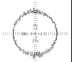 Figure 3 Roundness error caused by axial vibration
(2) The method of suppressing feed shaft vibration in CNC machine tools usually causes vibration of the machine shaft due to mismatched electromechanical systems. The purpose of driving optimization is to achieve the best matching of the electromechanical system, thereby obtaining the optimal and most stable dynamic performance. As shown in Figure 4, the servo drive of the machine tool axis includes three feedback loops, namely the position loop, speed loop, and current loop. When the feed shaft vibrates, the first step is to check whether the mechanical system has good lubrication and whether the transmission chain has sufficient stiffness; Secondly, further optimization of the servo motor should be carried out based on the mechanical maintenance situation. Manual optimization can be carried out by adjusting the position loop gain parameter MD32200 and the speed loop gain parameter 1407 until the servo shaft does not vibrate and the motion is stable.
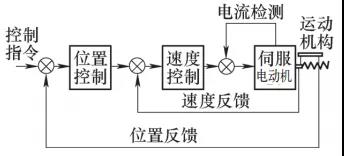 Figure 4 Servo System Block Diagram
three
Interpolation axis servo gain mismatch
The distance between each axis of the machining center should be exactly the same during the cycle of running a circle. If the milling process turns a circle into an ellipse, as shown in Figure 5, it indicates that the major axis is ahead of the minor axis during the interpolation motion of the two axes. For machine tools that have been used for many years, the first step is to inspect the mechanical structure of the machine tool's interpolation shaft, whether the transmission device is loose, and whether the wear is severe. Check the pre tightening of the screw and bearing for clearance adjustment, and compensate for the reverse clearance. After eliminating the above problems, the gain of the two interpolation shafts needs to be readjusted to ensure that the acceleration parameter MD32300 and position ring gain MD32200 of the two interpolation shafts are consistent.
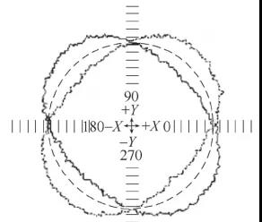 Figure 5: Inconsistent gain causing ellipses
four
Reverse jump
Reverse jump refers to when a machine tool axis is moving in the opposite direction, and the axis accelerates from negative speed to positive speed. When the axis speed passes through 0, the state of frictional force changes from static frictional force to dynamic frictional force. The required force is greater than normal motion, causing a short-term viscous pause at the reversing position due to a change in the state of frictional force.
(1) The Influence of Reverse Jump Error on Roundness Error In the milling process of a machining center, when the shaft is beyond the quadrant, the direction of the shaft speed changes, the shaft starts from zero speed, and the frictional force state changes accordingly, inevitably resulting in reverse jump. When one of the two interpolation axes has reached its maximum value while the speed of the other axis is 0, there will be a short period of stagnation, resulting in contour errors. As shown in Figure 6, the circle has four sharp corners at the quadrant, which is the reverse jump error caused by static friction.
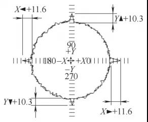 Figure 6 Roundness error caused by reverse jump error
(2) The adjustment method for reverse jump is mainly due to the change in friction state. Therefore, when reverse jump occurs, friction compensation should be added to the interpolation shaft. In Siemens CNC system, friction compensation is determined by the friction compensation value MD32520 and the friction compensation time constant MD32540.
For the adjustment of reverse jump, first set MD32500=1 (effective friction compensation), and then adjust the friction compensation value MD32520 and friction compensation time constant MD32540 corresponding to the jump axis. The size of the two parameter values can be adjusted according to Figure 7, and the impact on the quadrant point can be eliminated until the sharp point is crossed. It should be noted that the compensation value set should not be too large. When MD32520>150mm/min and MD32540>0.015s, it is necessary to first check whether the mechanical transmission is good, whether the speed loop gain and integration time are reasonable. Excessive static friction compensation may have a negative impact on surface quality.
 Figure 7 Friction Compensation Reference
five
epilogue
CNC machine tools are a complete organic whole, and the control of mechanical, electrical, and hydraulic systems is interconnected and mutually influential. Therefore, when analyzing and solving the factors affecting roundness error, there should be an overall concept and experience, and multiple aspects of detection, analysis, and diagnosis should be carried out until the root cause of the fault is identified.


