


The main techniques of drilling and machining
1.
Tips for using coolant
The correct use of coolant is crucial for achieving good drilling performance, as it directly affects chip removal, tool life, and hole quality during machining.
(1) How to use coolant
1) Internal cooling design
Internal cooling design is always the first choice to avoid chip blockage, especially when processing long chip materials and drilling deeper holes (greater than 3 times the aperture). For a horizontal drill bit, when coolant flows out of the drill bit, there should be no downward flow of cutting fluid over a length of at least 30cm.
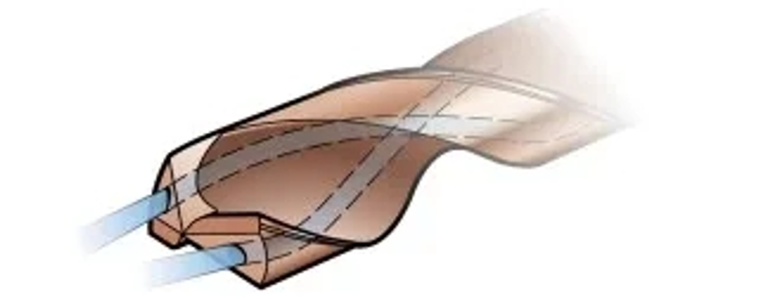
2) External cooling design
The use of external coolant can be used when the chips are well formed and the hole depth is shallow. To improve chip removal, there should be at least one coolant nozzle (or two nozzles if non rotating applications) located near the tool axis.
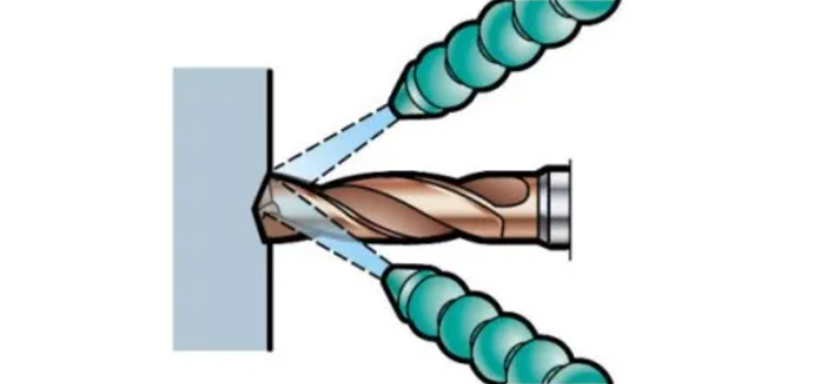
3) Dry drilling techniques without using coolant
Dry drilling is usually not recommended.
a) Can be used in applications with short chip materials and hole depths up to 3 times the diameter
b) Suitable for horizontal machine tools
c) Suggest reducing cutting speed
d) The tool life will decrease
It is recommended not to use dry drilling for:
a) Stainless steel materials (ISO M and S)
b) Interchangeable drill bit
4) High pressure cooling (HPC) (~70 bar)
The benefits of using high-pressure coolant are:
a) Due to the enhanced cooling effect, the tool life is longer
b) Improve the chip removal effect in the processing of stainless steel and other long chip materials, and may extend the tool life
c) Better chip removal performance, therefore higher safety
d) Provide sufficient flow rate based on the given pressure and hole size to maintain coolant supply
(2) Tips for using coolant
Please make sure to use soluble cutting oil (emulsion) containing EP (extreme pressure) additive. To ensure optimal tool life, the oil content in the oil-water mixture should be between 5-12% (when processing stainless steel and high-temperature alloy materials, it should be between 10-15%). When increasing the oil content of cutting fluid, it is necessary to check it with an oil separator to ensure that it does not exceed the recommended oil content.
When conditions permit, internal coolant is always preferred over external coolant.
Clean oil can improve lubrication efficiency and bring benefits in drilling stainless steel applications. Please make sure to use it together with EP additives. Both integral hard alloy drill bits and indexable blade drill bits can use clean oil and achieve good results.
Compressed air, mist cutting fluid, or MQL (micro lubrication) may become successful choices under stable working conditions, especially when processing certain cast iron and aluminum alloys. Due to the potential negative impact of temperature rise on tool life, it is recommended to reduce cutting speed.
2.
Chip control techniques
Blocking debris can cause radial movement of the drill bit, thereby affecting hole quality, drill bit lifespan and reliability, or leading to drill bit/blade breakage.
When chips can be smoothly discharged from the drill bit, chip formation is acceptable. The best way to identify it is to monitor during the drilling process. Continuous sound indicates good chip removal, while intermittent sound indicates chip blockage. Check the feed force or power monitor. If there is an abnormality, the cause may be chip blockage. View chips. If the chips are long and curved, but not curled, it indicates chip blockage. View holes. After debris blockage occurs, a rough surface will be visible.
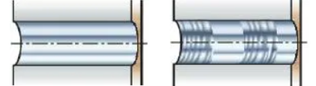
Good chip removal (left) and holes affected by chip blockage (right)
Tips for avoiding debris blockage:
1) Ensure the use of correct cutting parameters and drill bit/tool tip groove shape
2) Check chip shape - adjust feed rate and speed
3) Check the cutting fluid flow rate and pressure
4) Check the cutting edge. When the entire chip groove is not functioning, cutting edge damage/chipping may result in long chips
5) Check if cutting performance has changed due to new workpiece batches - adjust cutting parameters
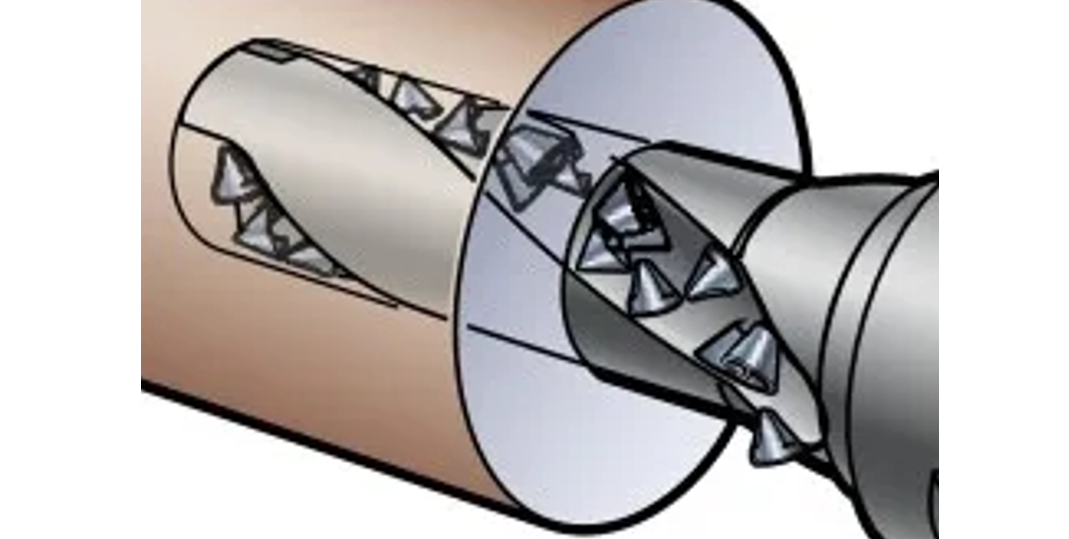
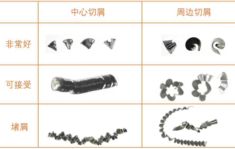
(1) Chips from interchangeable blade drills
The conical chips formed by the central blade are easily recognizable. The chips formed by the peripheral blades are similar to turning.
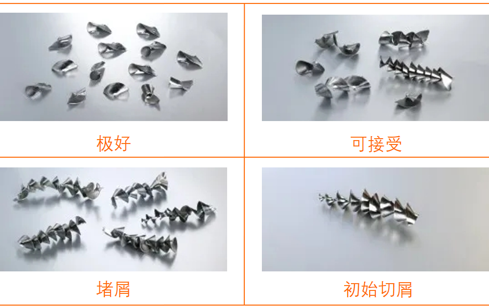
(2) Chips from integral hard alloy drill bits
A chip can be formed from the center to the periphery of the cutting edge. It is worth noting that the initial chips generated when drilling into the workpiece are always very long, but this will not cause any problems.
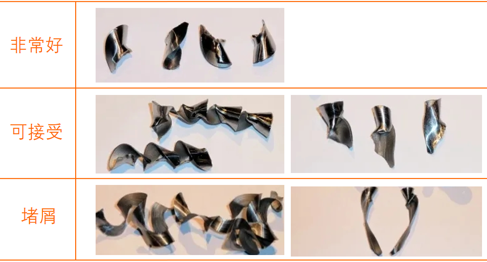
(3) Chips from interchangeable drill bits
3.
Control of feed and cutting speed
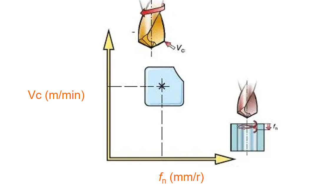
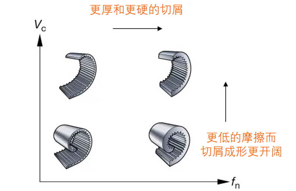
(1) The influence of cutting speed Vc (m/min)
In addition to material hardness, cutting speed is also the main factor affecting tool life and power consumption.
1) Cutting speed is the most important factor determining tool life
2) Cutting speed affects power Pc (kW) and torque Mc (Nm)
3) A higher cutting speed will generate higher temperatures and increase the wear of the rear tool surface, especially at the peripheral tool tip
4) When processing certain softer and longer chip materials (i.e. low-carbon steel), a higher cutting speed is beneficial for chip formation
Cutting speed too high:
a) The wear of the rear blade surface is too fast
b) Plastic deformation
c) Poor hole quality and oversized aperture
Cutting speed too low:
a) Generating debris tumors
b) Poor chip removal
c) Longer cutting time
(2) The influence of feed fn (mm/r)
1) Impact on chip formation, surface quality, and hole quality
2) Impact power Pc (kW) and torque Mc (Nm)
3) The high feed will affect the feed force Ff (N), which should be considered when the working condition is unstable
4) Affects mechanical stress and thermal stress
High feed rate:
a) Hard chip breakage
b) Short cutting time
c) Less tool wear but increased risk of drill bit edge breakage
d) Reduced hole quality
Low feed rate:
a) The chips are longer and thinner
b) Quality improvement
c) Accelerated tool wear
d) Longer cutting time
e) When drilling thin and rigid parts, a low feed rate should be maintained
4
Tips for obtaining high-quality holes
(1) Chip removal
Ensure that the chip removal performance meets the requirements. Chip blockage affects hole quality, reliability, and tool life. The groove shape and cutting parameters of the drill bit/blade are crucial.
(2) Stability, tool clamping
Use the shortest possible drill bit. Use a refined rigid knife handle with minimal jumping. Ensure that the spindle of the machine tool is in good condition and accurately aligned. Ensure that the parts are fixed and stable. Apply the correct feed rate to irregular surfaces, slopes, and intersecting holes.
(3) Tool life
Check the wear of the blades and preset the tool life management program. The most effective method is to use the feed force monitor to monitor drilling.
(4) Maintenance
Regularly replace the blade clamping screws. Clean the blade holder first, then replace the blade and make sure to use a torque wrench. Before re grinding the overall hard alloy drill bit, do not exceed the maximum wear amount.
5
Drilling techniques for different materials
(1) Low carbon steel drilling techniques
For low-carbon steel commonly used for welding parts, chip formation may be a challenge. The lower the hardness, carbon content, and sulfur content of steel, the longer the chips produced.
1) If the problem is related to chip forming, increase the cutting speed VC and reduce the feed fn (please note that when processing ordinary steel, the feed should be increased).
2) Use high-pressure and internal coolant supply.
(2) Drilling techniques for austenitic and duplex stainless steel
Austenitic, duplex, and super duplex materials may lead to issues related to chip forming and chip removal.
1) The correct groove shape is crucial as it can help the chips form correctly and aid in their discharge. Generally speaking, it is best to use sharp cutting edges. If the problem is related to chip forming, increasing the feed fn will make the chips more prone to breakage.
2) Internal cooling design, high pressure.
(3) CGI (vermicular graphite cast iron) drilling techniques
CGI usually does not require special attention. It will produce larger chips than gray cast iron, but the chips are prone to breakage. The cutting force is higher, which will affect the tool life. Need to use super wear-resistant materials. There will be the same typical tool tip wear as all cast iron.
1) If the problem is related to chip forming, increase the cutting speed Vc and reduce the feed fn.
2) Internal cooling design.
(4) Aluminum alloy drilling techniques
Burr formation and chip removal may become issues. It may also lead to short tool life due to adhesion.
1) To ensure optimal chip formation, use low feed and high cutting speeds.
2) To avoid short tool life, it may be necessary to test different coatings to minimize adhesion. These coatings may include diamond coatings, or they may not use any coatings at all (depending on the substrate).
3) Use high-pressure emulsion or mist coolant.
(5) Drilling techniques for titanium alloys and high-temperature alloys
Work hardening of the hole surface has an impact on subsequent processes. Difficulty in achieving good chip removal performance.
1) When selecting groove shapes for processing titanium alloys, it is best to have sharp cutting edges. A sturdy groove shape is crucial when processing nickel based alloys. If work hardening issues occur, try increasing the feed rate.
2) Improved performance with high-pressure coolant up to 70 bar.
(6) Drilling Techniques for Hardened Steel
Obtain an acceptable tool life.
1) Reduce cutting speed to reduce heat. Adjust the feed rate to obtain acceptable and easily discharged chips.
2) High concentration mixed emulsion.


