


Complete Collection of Aluminum Product Processing Techniques
Aluminum is the most widely used and widely used metal material among non-ferrous metals, and its application range is constantly expanding. The aluminum products produced using aluminum materials are diverse and countless, with over 700000 types according to statistics. From the construction and decoration industry to the transportation and aerospace industries, various industries have different needs. Today, the editor will introduce the processing technology of aluminum products and how to avoid processing deformation.
The advantages and characteristics of aluminum are as follows:
1. Low density. The density of aluminum is about 2.7g/cm3. Its density is only one-third of that of iron or copper.
2. High plasticity. Aluminum has good ductility and can be made into various products through pressure processing methods such as extrusion and stretching.
3. Corrosion resistance. Aluminum is a highly negatively charged metal that forms a protective oxide film on its surface under natural conditions or anodic oxidation, and has much better corrosion resistance than steel.
4. Easy to reinforce. The strength of pure aluminum is not high, but it can be improved by anodizing.
5. Easy surface treatment. Surface treatment can further improve or alter the surface properties of aluminum. The aluminum anodizing process is quite mature and stable in operation, and has been widely used in the processing of aluminum products.
6. Good conductivity, easy to recycle.
Aluminum product processing technology
Punching of aluminum products
1. Cold punching
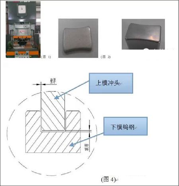
Use material aluminum particles. Using extrusion machines and molds for one-time molding is suitable for cylindrical products or product shapes that are difficult to achieve in stretching processes, such as elliptical, square, and rectangular products. (As shown in Figure 1 Machine, Figure 2 Aluminum Particle, and Figure 3 Product)
The tonnage of the machine used is related to the cross-sectional area of the product. The gap between the upper die punch and the lower die tungsten steel is the wall thickness of the product, and the vertical gap to the bottom dead center when the upper die punch and the lower die tungsten steel are pressed is the top thickness of the product. (As shown in Figure 4)
Advantages: Short mold opening cycle and lower development cost compared to stretching molds.
Disadvantages: The production process is long, the product size fluctuates greatly during the process, and the labor cost is high.
2. Stretch
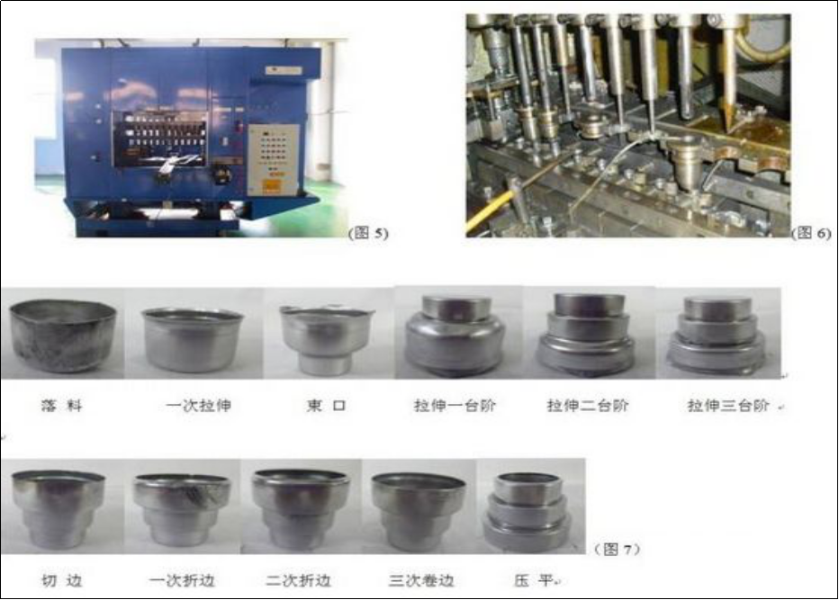
Use aluminum sheet material. Using a continuous molding machine and mold for multiple deformations to meet the shape requirements, suitable for non cylindrical bodies (aluminum products with bending). (As shown in Figure 5 Machine, Figure 6 Mold, and Figure 7 Product)
Advantages: Complex and repeatedly deformed products have stable dimensional control during the production process, and the product surface is relatively smooth.
Disadvantages: High mold cost, relatively long development cycle, high requirements for machine selection and accuracy.
Surface treatment of aluminum products
1. Sandblasting (shot blasting)
The process of cleaning and roughening metal surfaces using the impact of high-speed sand flow.
This method of surface treatment for aluminum parts can achieve a certain degree of cleanliness and different roughness on the surface of the workpiece, improve the mechanical properties of the workpiece surface, thereby enhancing the fatigue resistance of the workpiece, increasing its adhesion to the coating, prolonging the durability of the coating, and also facilitating the leveling and decoration of the coating. We often see this process in various products of Apple.
2. Polishing
A machining method that utilizes mechanical, chemical, or electrochemical effects to reduce the surface roughness of workpieces, in order to obtain a bright and flat surface. The polishing process mainly includes mechanical polishing, chemical polishing, and electrolytic polishing. Aluminum parts can achieve a mirror like effect similar to stainless steel after mechanical polishing and electrolytic polishing. This process gives people a feeling of high-end, simple, and fashionable future.
3. Wire drawing
Metal wire drawing is the manufacturing process of repeatedly scraping aluminum plates with sandpaper to create lines. Drawing can be divided into straight line drawing, irregular line drawing, spiral line drawing, and thread drawing. The metal wire drawing process can clearly show every tiny trace, thus giving a fine hair luster in the metal matte, and the product combines fashion and technology.
4. High gloss cutting
Using a precision carving machine, the diamond knife is reinforced on the high-speed rotating (usually 20000 rpm) spindle of the precision carving machine to cut parts, creating local bright areas on the surface of the product. The brightness of cutting highlights is influenced by the speed of the milling drill bit. The faster the drill bit speed, the brighter the cutting highlight, while the opposite is true, making it darker and more prone to tool lines. High gloss and high gloss cutting are particularly common in the application of mobile phones, such as the iPhone 5. In recent years, some high-end TV metal frames have adopted high gloss milling technology, combined with anodizing and wire drawing processes, making the TV overall full of fashion and technological sharpness.
5. Anodization
Anodizing refers to the electrochemical oxidation of metals or alloys, in which aluminum and its alloys form an oxide film on aluminum products (anodes) under corresponding electrolytes and specific process conditions due to the action of applied current. Anodizing not only solves the defects in surface hardness and wear resistance of aluminum, but also prolongs its service life and enhances its aesthetics. It has become an indispensable part of aluminum surface treatment and is currently the most widely used and successful process.
6. Dual color anode
Two color anode refers to anodizing a product and assigning different colors to specific areas. The dual color anodizing process is less commonly used in the television industry due to its complexity and high cost; But the contrast between the two colors better reflects the high-end and unique appearance of the product.
Process measures and operational skills to reduce aluminum processing deformation
There are many reasons for the deformation of aluminum parts during processing, which are related to material, part shape, production conditions, etc. There are mainly the following aspects: deformation caused by internal stress in the blank, deformation caused by cutting force and cutting heat, and deformation caused by clamping force.
Process measures to reduce processing deformation
1. Reduce the internal stress of wool cultivation
Natural or artificial aging and vibration treatment can partially eliminate the internal stress of the blank. Pre processing is also an effective process method. Due to the large margin, there is also a large amount of deformation after processing for the rough parts of the fat head and big ears. If the excess parts of the blank are pre processed and the excess of each part is reduced, it can not only reduce the processing deformation of subsequent processes, but also release some internal stress after being left for a period of time after pre processing.
2. Improving the cutting ability of cutting tools
The material and geometric parameters of cutting tools have an important impact on cutting force and cutting heat. The correct selection of cutting tools is crucial for reducing part machining deformation.
1) Reasonably select the geometric parameters of the cutting tool.
① Front angle: While maintaining the strength of the cutting edge, selecting a larger front angle can not only sharpen the edge, but also reduce cutting deformation, making chip removal smooth, thereby reducing cutting force and cutting temperature. Avoid using negative rake angle tools.
② Back angle: The size of the back angle has a direct impact on the wear of the back cutting surface and the quality of the machined surface. Cutting thickness is an important condition for selecting the back angle. During rough milling, due to the large feed rate, heavy cutting load, and high heat generation, it is required that the tool has good heat dissipation conditions. Therefore, a smaller back angle should be selected. When precision milling, it is required to have a sharp edge to reduce friction between the back cutting surface and the machining surface, and to reduce elastic deformation. Therefore, a larger back angle should be selected.
③ Spiral angle: To ensure smooth milling and reduce milling force, the spiral angle should be selected as large as possible.
④ Main deviation angle: Reducing the main deviation angle appropriately can improve heat dissipation conditions and lower the average temperature of the processing area.
2) Improve tool structure.
① Reduce the number of milling cutter teeth and increase the chip holding space. Due to the high plasticity of aluminum materials, there is significant cutting deformation during processing, which requires a larger chip holding space. Therefore, it is advisable to have a larger chip holding groove bottom radius and fewer milling cutter teeth.
② Fine grinding of blade teeth. The roughness value of the cutting edge of the cutter teeth should be less than Ra=0.4um. Before using a new knife, a fine oilstone should be used to gently grind the front and back of the blade teeth a few times to eliminate any remaining burrs and slight serrations when grinding the blade teeth. In this way, not only can cutting heat be reduced, but cutting deformation is also relatively small.
③ Strictly control the wear standards of cutting tools. After tool wear, the surface roughness value of the workpiece increases, the cutting temperature rises, and the deformation of the workpiece increases accordingly. Therefore, in addition to selecting tool materials with good wear resistance, the tool wear standard should not exceed 0.2mm, otherwise it is easy to produce chip deposits. During cutting, the temperature of the workpiece should generally not exceed 100 ℃ to prevent deformation.
3. Improving the clamping method of workpieces
For thin-walled aluminum parts with poor rigidity, the following clamping methods can be used to reduce deformation:
① For thin-walled liner parts, if a three jaw self centering chuck or spring chuck is used to clamp radially, once loosened after processing, the workpiece will inevitably deform. At this point, the method of compressing the axial end face with good rigidity should be used. Using the internal hole of the part for positioning, make a threaded through shaft and insert it into the internal hole of the part. Use a cover plate to press the end face tightly and then tighten it with a nut. When processing the outer circle, clamping deformation can be avoided, thus achieving satisfactory machining accuracy.
② When processing thin-walled thin plate workpieces, it is best to use vacuum suction cups to obtain evenly distributed clamping force, and then use smaller cutting amounts to process, which can effectively prevent workpiece deformation.
Additionally, the stuffing method can also be used. To increase the process rigidity of thin-walled workpieces, media can be filled inside the workpiece to reduce deformation during clamping and cutting processes. For example, injecting urea melt containing 3% to 6% potassium nitrate into the workpiece, and after processing, immersing the workpiece in water or alcohol can dissolve and pour out the filler.
4. Reasonably arrange the process
During high-speed cutting, due to large machining allowance and intermittent cutting, the milling process often generates vibration, which affects machining accuracy and surface roughness. Therefore, the CNC high-speed cutting process can generally be divided into rough machining, semi precision machining, corner cleaning machining, precision machining and other processes. For parts with high precision requirements, sometimes secondary semi precision machining is required, followed by precision machining. After rough machining, the parts can be naturally cooled to eliminate the internal stress generated by rough machining and reduce deformation. The margin left after rough machining should be greater than the deformation, generally 1-2mm. During precision machining, the surface of the parts should maintain a uniform machining allowance, generally ranging from 0.2 to 0.5mm, to keep the cutting tool in a stable state during the machining process. This can greatly reduce cutting deformation, achieve good surface machining quality, and ensure the accuracy of the product.
Operational skills for reducing machining deformation
The deformation of aluminum parts during the machining process is not only due to the above reasons, but also due to the importance of operational methods in practical operations.
1. For parts with large machining allowance, in order to have better heat dissipation conditions during the machining process and avoid heat concentration, symmetrical machining should be used during machining. If there is a 90mm thick sheet metal that needs to be machined to 60mm, if one side is milled and the other side is milled immediately, and the flatness reaches 5mm when machining to the final size in one go; If repeated feed symmetric machining is used, each side is machined twice to the final size, ensuring a flatness of 0.3mm.
2. If there are multiple cavities on the sheet metal part, it is not advisable to use the sequential processing method of one cavity for each cavity during processing, as this can easily cause uneven stress on the part and deformation. Adopting multiple layers of processing, each layer is processed simultaneously to all cavities as much as possible, and then the next layer is processed to make the parts uniformly stressed and reduce deformation.
3. Reduce cutting force and cutting heat by changing the cutting amount. Among the three elements of cutting parameters, the back feed has a significant impact on cutting force. If the machining allowance is too large and the cutting force of a single pass is too large, it will not only cause deformation of the parts, but also affect the rigidity of the machine tool spindle and reduce the durability of the tool. If the amount of back cutting is reduced, it will greatly reduce production efficiency. However, high-speed milling is commonly used in CNC machining to overcome this challenge. While reducing the amount of back cutting, as long as the feed rate is correspondingly increased and the machine speed is increased, the cutting force can be reduced while ensuring machining efficiency.
4. The order of cutting also needs to be carefully considered. Rough machining emphasizes improving machining efficiency and pursuing a cutting rate per unit time. Generally, reverse milling can be used. Cut off excess material on the surface of the blank at the fastest speed and in the shortest time possible, and basically form the geometric contour required for precision machining. Precision machining emphasizes high precision and quality, and it is advisable to use forward milling. Because the cutting thickness of the cutter teeth gradually decreases from maximum to zero during forward milling, the degree of work hardening is greatly reduced, while also reducing the degree of deformation of the parts.
5. Thin walled workpieces undergo deformation during machining due to clamping, which is difficult to avoid even during precision machining. To minimize the deformation of the workpiece, the clamping part can be loosened before the final size is reached during precision machining, allowing the workpiece to freely return to its original state. Then, it can be slightly tightened to ensure that the workpiece is firmly clamped (completely based on hand feel), which can achieve the desired machining effect. In short, it is best for the clamping force to act on the supporting surface, and the clamping force should act in the direction of good workpiece rigidity. On the premise of ensuring that the workpiece is not loose, the smaller the clamping force, the better.
6. When processing parts with a cavity, it is advisable not to let the milling cutter directly penetrate the part like a drill bit, resulting in insufficient chip space for the milling cutter, unsmooth chip removal, overheating, expansion, tool breakage, and other adverse phenomena. First, use a drill bit of the same size or one size larger than the milling cutter to drill the tool hole, and then use the milling cutter to mill it. Alternatively, CAM software can be used to produce spiral cutting programs.


