


Accurate tool alignment method for CNC lathes!
This article is a very practical one. Firstly, it introduces the principle and tool alignment method commonly used in CNC lathes; Next, four manual trial cutting and tool alignment methods for the Huazhong Century Star CNC turning system were introduced; In order to improve its tool alignment accuracy, an automatic trial cutting method controlled by a program was designed based on the idea of "automatic trial cutting → measurement → error compensation", and four precise tool alignment methods were summarized and introduced
The principle and tool alignment approach of CNC lathe trial cutting
A deep understanding of the tool alignment principle of CNC lathes is of guiding significance for operators to maintain a clear tool alignment mindset, master tool alignment operations proficiently, and propose new tool alignment methods. The essence of tool alignment is to determine the position of the program origin of the workpiece coordinate system that changes with programming in a unique machine coordinate system. The main task of tool alignment is to obtain the machine tool coordinates of the starting point of the reference tool program and determine the tool offset of the non reference tool relative to the reference tool.
This article makes the following agreement to explain the principle and idea of the trial cutting method for tool alignment: using the Huazhong Century Star teaching type turning system HNC-21T (application software version number 5.30); Set the workpiece coordinate system using the G92 command with the center of the right end face of the workpiece as the program origin; Diameter programming, the workpiece coordinates of the program starting point H are (100, 50); There are four knives installed on the tool holder: the first knife is a 90 ° outer circle rough turning knife, the second reference knife is a 90 ° outer circle fine turning knife, the third knife is a cutting knife, and the fourth knife is a 60 ° triangular thread knife (all examples cited throughout the text are the same).
As shown in Figure 1, the reference tool is aligned according to the idea of "manually cutting the outer circle and end face of the workpiece, recording the X and Z machine coordinates of the trial cutting point A displayed on the CRT, then pushing out the machine coordinates of the program origin O, and finally pushing out the machine coordinates of the program origin H.". According to the relationship between the machine tool coordinates of point A and point O: XO=XA - Φ d. ZO=ZA, the machine coordinate of program origin O can be derived. Based on the workpiece coordinates of H relative to point O as (100,50), the machine tool coordinates of point H are finally derived as follows: XH=100- Φ d. ZH=ZA+50. The workpiece coordinate system established in this way is based on the position of the reference tool tip.
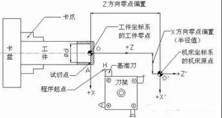
Figure 1 Schematic diagram of manual trial cutting and tool alignment
As shown in Figure 2, due to the different extensions and positions of each tool holder in the X and Z directions, when the non reference tool is rotated to the machining position, the tool tip position B is offset relative to point A, and the previously established workpiece coordinate system is no longer applicable. In addition, each tool will also experience varying degrees of wear during use, so the tool offset and wear value of each tool need to be compensated. The basic principle of obtaining the offset of each tool is that each tool is aligned with a certain reference point on the workpiece (such as point A or point O in Figure 1). Due to the different machine coordinates displayed on CRT, the machine coordinates of the non reference tool at that point are manually calculated or subtracted from the machine coordinates of the reference tool at the same point through system software calculation to obtain the tool offset of each non reference tool.
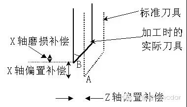
Figure 2 Tool Bias and Wear Compensation
Due to various factors, the accuracy of manual trial cutting tool alignment is very limited, and this stage of tool alignment is referred to as rough tool alignment. To obtain more accurate results, as shown in Figure 3, a simple automatic trial cutting program is designed within the machining allowance range of the part before processing. Through the idea of "automatic trial cutting → measurement → error compensation", the starting position of the benchmark tool program and the tool offset of the non benchmark tool are repeatedly adjusted, so that the error between the program processing instruction value and the actual measurement value meets the accuracy requirements. This stage of tool alignment is called precise tool alignment.
Since ensuring that the starting point of the reference tool program is in a precise position is a prerequisite for obtaining accurate non reference tool offset, the former is generally corrected before the latter is corrected.
Taking into account the tool alignment in these two stages, the basic operation process of the trial cutting method is as follows: manually trial cutting with a reference tool to obtain the machine tool coordinates of the tool alignment reference point → manually calculating or automatically obtaining the tool offset of each non reference tool → the reference tool is at the approximate starting position of the program → the reference tool is adjusted using the trial cutting program, and after measuring the size, the tool holder is moved in a step-by-step or MDI manner for error compensation, Correct the position of the starting point of the program → Repeatedly call the trial cutting program for the non reference tool, and correct the tool offset on the basis of the original tool offset → The reference tool remains at the accurate starting point of the program.
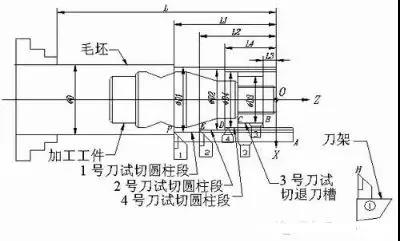
Figure 3 Schematic diagram of multi blade trial cutting and tool alignment
Summary of Two Rough Knife Alignment Methods
The preparation work for tool alignment is the same for each of the following methods: Press F2 key under the system MDI function submenu to enter the tool deviation table; Use the ▲ and keys to move the blue light bar to the corresponding tool offset position for each knife, and press the F5 key; Modify the X and Z offset data for tool offset numbers # 0000, # 0001, # 0002, # 0003, and # 0004 to zero, and then press the F5 key.
1. Select the reference tool as the standard tool and automatically set the tool offset method
As shown in Figures 1 and 4, the steps for tool alignment are as follows:
1) Use the ▲ and keys to move the blue bright bar to align with the tool deviation # 0002 position of the 2nd reference tool. Press the F5 key to set the 2nd tool as the standard tool, and the row will turn into a red bright bar.
2) Use a reference knife to cut the right end face of the workpiece, and record the Z-machine coordinate of the cutting point A; Try cutting the outer circle of the workpiece, record the X machine coordinate of point A, stop the machine after retracting the tool, and measure the outer diameter of the cut shaft segment Φ D.
3) The benchmark knife returns to point A through "jog+step" according to the recorded value, and enters the trial cutting diameter and trial cutting length columns in the tool deviation table separately Φ D and zero.
4) Retract the tool, select a tool number other than the reference tool and manually change the tool. Align the tool tips of each non reference tool with point A through a "jog+step" method while rotating the spindle, and then input them into the trial cutting diameter column and trial cutting length column of the corresponding tool deviation number Φ D and zero, the tool biases of each non reference tool will be automatically displayed in the X and Z offset columns.
5) After the benchmark knife returns to point A, MDI runs "G91 G00/or G01 X [100]"- Φ D] Z50, place it at the starting position of the program.
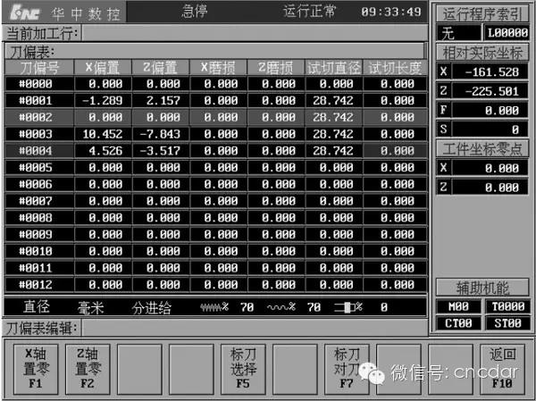
Figure 4: Schematic diagram of automatic setting of tool offset for benchmark knives
2. Set the coordinate of the reference tool to zero at the tool alignment reference point, and automatically display the tool offset method
As shown in Figures 1 and 5, the steps for tool alignment are as follows:
1) Same as step (2) above.
2) The benchmark knife returns to the trial cutting point A through a "jog+step" method according to the recorded value.
3) Press F1 to "zero X-axis" and F2 to "zero Z-axis" on the interface in Figure 4, and the "relative actual coordinates" displayed on the CRT will be (0,0).
4) Manually change the non reference tool to align its tip visually with point A. At this point, the value of "relative to actual coordinates" displayed on the CRT is the tool offset of the tool relative to the reference tool. Use the ▲ and keys to move the blue bright bar to the tool offset number of the non reference tool, record and input it to the corresponding position.
5) Same as step (5) above.

Figure 5 Schematic diagram of automatic display of tool offset at the zero coordinate of the tool reference point for the reference tool
3 multi blade trial cutting of outer circular shaft segments, manually calculated to obtain tool offset method
As shown in Figure 6, the system manually aligns tools 1, 2, and 4, cuts a step axis, records the machine coordinates of the cutting endpoints of each tool (as shown in points F, E, and D in Figure 6), and measures the diameter and length of each segment. Replace the No. 3 cutting blade, cut a back groove, align the right tip of the cutting blade with the tool, record the coordinates of point B, and measure the position shown in the diagram Φ D3 and L3. After obtaining the above data, according to the coordinate increment relationship between the F, E, D, and B points corresponding to each tool and the program origin O, it can be determined that the machine coordinate of the program origin of the reference tool is (X2)- Φ D2+100, Z2-L2+50); Moreover, the machine tool coordinates corresponding to the program origin for each non reference tool can be derived and the tool offset can be obtained through manual calculation. The calculation method is shown in Table 1, and the recorded and calculated values can be filled in the corresponding spaces. It should be noted that the trial cutting length refers to the directed distance in the Z direction between the zero point of the workpiece coordinate and the end point of the trial cutting, and is determined in the positive and negative directions according to the direction of the coordinate axis.

Figure 6 Schematic diagram of multi blade manual trial cutting

Table 1 Calculation Table for Tool Bias of Non reference Knives
The trial cutting process of this method is simple, eliminating the step of visually aligning the trial cutting points, but the tool offset needs to be manually calculated. If the calculation table containing the calculation formula is printed out and the values are filled in the corresponding spaces for calculation, the tool offset can be quickly calculated.
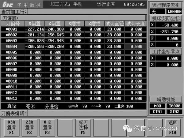
Figure 7: Schematic diagram of automatic tool alignment in the CNC system of Century Star turning
4th Century Star Turning CNC System, Multi Tool Automatic Alignment Method
The above knife alignment methods are all relative knife deviation methods. HNC-21T has undergone parameter settings and system debugging by professional personnel, and users can also choose the "absolute tool deviation method" for tool alignment. The absolute tool deviation method is slightly different from the relative tool deviation method mentioned above in the programming of machining. It is not necessary to establish the workpiece coordinate system using G92 or G54, nor to cancel the tool compensation. For example, please refer to program O1005. The steps for tool alignment are as follows: after the system returns to zero, as shown in Figure 6, each tool is manually cut into a cylindrical section. After measuring the diameter and length dimensions, the trial cutting diameter corresponding to the tool offset number is filled in the trial cutting length column as shown in Figure 7. Based on the principle described in "Multiple tool trial cutting of outer circular shaft segments, manually calculating the tool offset method", the system software can automatically calculate the machine coordinates of the program origin for each tool, Thus achieving the goal of automatic knife alignment. This knife alignment method is the quickest and particularly suitable for industrial production.
Summary of 5 Precise Knife Alignment Methods
The overall idea for the precise tool alignment stage is "automatic trial cutting → measurement → error compensation". There are two types of error compensation: for the MDI operation of the reference tool or for the compensation of the program starting position of the step moving tool holder; For non reference tools, compensate for their tool offset or wear value. To avoid confusion in recording, design a table as shown in Table 2 to record and calculate numerical values.
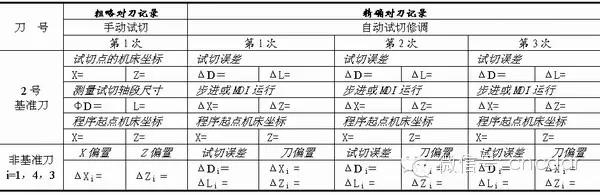
Table 2 Trial Cutting Method Knife Setting Record (Unit: mm)
1. After correcting the starting position of the benchmark tool correction program, adjust the bias method of each non benchmark tool separately
As shown in Figure 3, the steps for tool alignment are as follows:
1) The reference tool is at the starting position of the program after rough tool alignment, and the offset of each non reference tool is input to the corresponding position on the tool deviation table.
2) Call processing Φ D2 × L2's O1000 program trial cut.
3) Measure the diameter and length of the cutting shaft segment, compare it with the program command value, and calculate the error.
4) Step by step movement or MDI operation error value, adjust the starting position of the program.
5) According to the measured dimensions, dynamically modify the command values underlined in the O1000 program and save the program. Repeat steps (2) and (3) until the starting point of the reference tool program is corrected within the allowable accuracy range. Record the machine tool coordinates of the corrected starting point of the program and reset the coordinates to zero.
6) Call the O1001 (Knife 1 and 4) and O1002 (Knife 3) programs respectively for trial cutting, and measure the diameter of each section Φ Di and length Li (i=1, 4, 3).
7) Perform error compensation according to the method shown in Table 3.
8) Repeat steps (6) to (7) until the machining error is within the accuracy range, and the reference tool stops at the starting position of the program without moving.

Table 3 Example of Error Compensation between Actual Measurement Dimensions and Program Instruction Values for Automatic Trial Cutting of Cylindrical Axis Segments (Unit: mm)
2. Method of adjusting the starting position of the program for each knife separately
The principle of knife alignment in this method is that each knife corrects its program starting position, indirectly ensuring alignment with the same program starting position.
As shown in Figure 3, the steps for tool alignment are as follows:
1) The No. 2 reference tool is at the starting position of the program after rough tool alignment, and all non reference tool offsets are recorded and modified to zero.
2) The steps up to (5) are the same as the tool alignment steps with the same serial number as the first precise tool alignment method.
(6) Replace the non reference tool separately, use the rough tool offset recorded as the relative coordinates of the starting point of the non reference tool program, call the O1000 program for trial cutting, and measure the diameter of each segment separately Φ Compare Di and length Li (i=1, 4, 3) with the program instruction value to determine the difference.
(7) Step by step movement or MDI operation of the tool holder for error compensation, adjust the program starting position of each non reference tool separately.
(8) Repeat steps (6) and (7) until the positions of the starting points of each non reference tool program are within the allowable accuracy range.
(9) Take the relative coordinates displayed by CRT as the new tool offset and input them into the X and Z offset columns of the corresponding tool offset number in the tool offset table. This method is simple and convenient, and the corrected tool offset is directly obtained from the relative coordinates of the machine displayed on the CRT, avoiding manual calculation errors and achieving high tool alignment accuracy.
3. After adjusting the starting position of the benchmark tool program, simultaneously adjust all non benchmark tool biases
This method is basically the same as the first accurate tool setting method, the only difference is that the program called in step (7) calls the O1003 program processed by three cutters at the same time (O1004 removes the processing section of tool 2 and is the O1003 program), and the other steps are the same.
Six Four Knives Simultaneously Trimming Method
If the relative tool offset method is used for rough tool alignment, first input the tool offsets of each non reference tool obtained to the corresponding positions on the tool offset table, run the O1004 program processed by four tools, and measure the diameters of each segment separately Φ Di and length Li (i=2, 1, 4, 3), calculate the machining error. For the reference knife, use MDI operation or step-by-step movement to compensate for the error value of the tool holder, and adjust the starting position of the program; For non reference tools, on the one hand, the tool offset is corrected based on the original tool offset, and the new tool offset is re entered into the X and Z offset columns of the tool offset table; On the other hand, the machining error of the reference tool should also be filled in the wear column of this row. If the absolute tool deviation method is used for rough tool alignment, call the O1005 program for trial cutting, and compensate for the machining errors of each tool in the wear column corresponding to its tool deviation number.


